ELECTRICAL CIRCUITS & SIMULATION LAB
Objective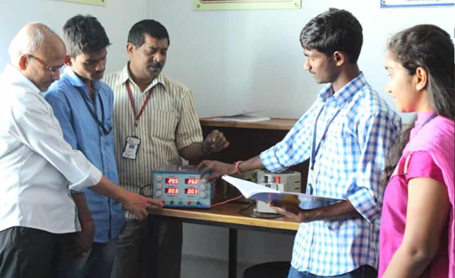
|
Principles of electrical circuits and systems. Basic circuit elements (resistance, inductance, mutual inductance, capacitance, independent and dependent controlled voltage, and current sources). Topology of electrical networks; Kirchhoff ’s laws; node and mesh analysis; DC circuit analysis; operational amplifiers; transient and sinusoidal steady-state analysis; AC circuit analysis; first- and second-order circuits; Bode plots; and use of computer simulation software to solve circuit problems. Laboratory experiments supporting theoretical principles presented in ENGR 2305 involving DC and AC circuit theory, network theorems, time, and frequency domain circuit analysis. Introduction to principles and operation of basic laboratory equipment; laboratory report preparation. |
| Major Equipments | 1. Stablizer 2. Regulated Power Supply 3. DC Ammeter 4. DC Volt Meter 5. Multi Meter |
ELECTRICAL MEASUREMENTS LAB
Objective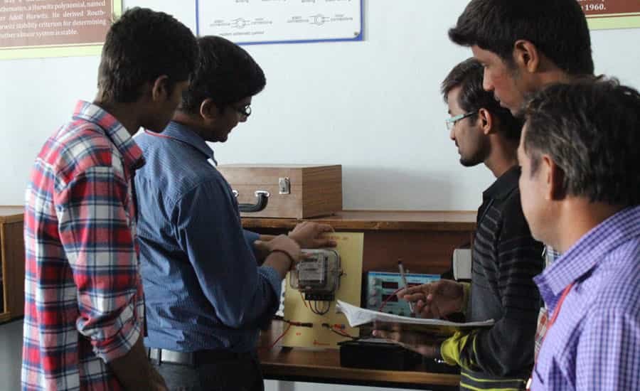
|
This laboratory, the students are expected to get hands-on experience in using the basic measuring devices used in electrical engineering and in interpreting the results of measurement operations in terms of the concepts introduced in the first electrical circuits course. Each student will get a thorough understanding of the equipment and concepts. |
| Major Equipments | 1. 1-phase energy meter 2. Kelvin double bridge. 3. 3-phase reactive power 4. Crompton potentiometer 5. Maxwell bridge 6. Measurement parameter of choke coil 7. LVDT kit 8. Strain gauge 9. Transformer oil kit 10. Schering bridge 11. Anderson bridge |
ELECTRICAL MACHINES LAB
Objective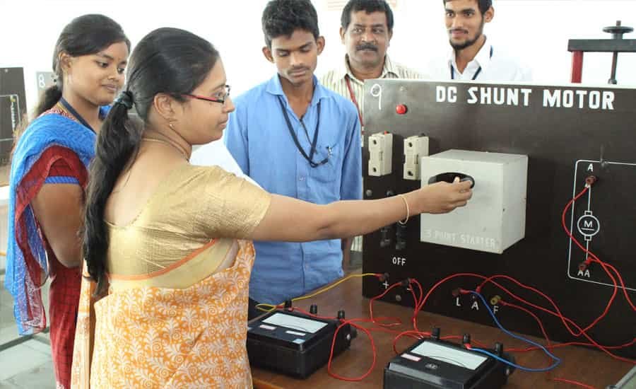
|
The objective of the laboratory is to provide the students a chance to put theory into practice. It also encourages the students to troubleshoot the system in organized and established manner. This lab gives the students the first hand chance to get familiar with basic machines which will be useful in power systems and power electronics courses. Besides, the lab instills in the students the awareness and practice of safety. |
| Major Equipments | 1. Panels for DC motor& Alternator with starters & terminals and fuses 2. Alternator coupled to DC shunt motor,3-ph,415V,3.5KVA,5.2A,1500rpm 3. Panel for dc shunt motor and dc shunt generator with starters & terminals and fuses 4. DC shunt motor coupled to DC shunt generator,5HP motor,3.5KW g/r 5. Panel for shunt motor coupled with shunt generator 6. DC shunt motor coupled to DC shunt generator 7. Panel for shunt motor series generator 8. DC shunt motor coupled to DC series generator,5HP motor,3.7KW g/r 9. Panel for shunt motor coupled with compound generator 10. DC shunt motor coupled to DC compound generator 11. Panel for series motor coupled with series generator 12. DC series motor coupled series generator5HP 13. Panels for DC shunt motors with starters& terminals and fuses(3) 14. DC shunt motor,5HP,230V,1500rpm 15. Panels for DC shunt motors with starters& terminals and fuses(3) 16. DC shunt motor,5HP,230V,1500rpm 17. Panel for shunt motor with mechanical loading 18. DC shunt motor with mechanical loading5HP 19. Panel for dc compound motor 20. DC compound motor with mechanical loading, 5HP 21. Panel for Synchronous Motor 22. Synchronous Motor with mechanical loading arrangement 23. Panels for Transformer with Dimmer 24. Panels for DC motor& Alternator with starters & terminals and fuses 25. DC shunt motor (5HP)coupled to 3KVA separately excited alternator |
POWER ELECTRONICS AND SIMULATION LAB
Objective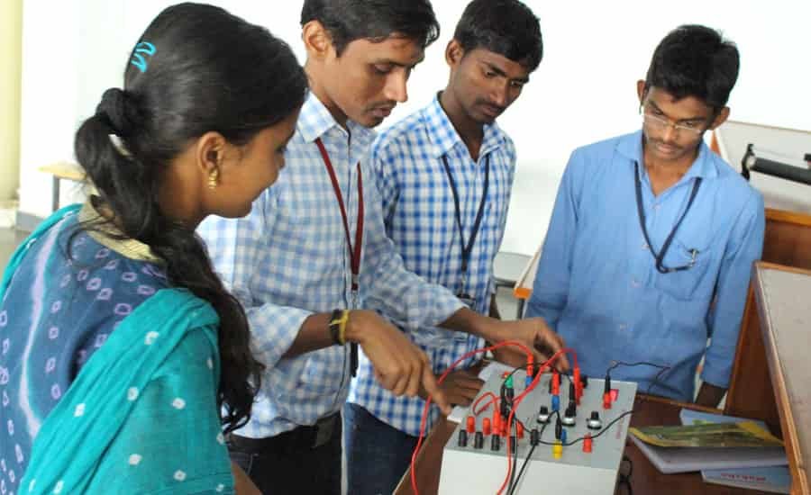
|
To study the characteristics of various power electronic devices and analyze firing circuits and commutation circuits of SCR. To analyze the performance of single–phase and three–phase full– wave bridge converters, single–phase dual converter with both resistive and inductive loads. To understand the operation of AC voltage controller and cyclo converter with resistive and inductive loads. To understand the working of Buck converter, Boost converter, single–phase bridge inverter and PWM inverter |
| Major Equipments | 1. Static Characteristics Of SCR, MOSFET, IGBT 2. Gate Firing Circuits For SCR
4. 1-PH Cyclo-Converter power unit 5. 1-PH Half Controlled Bridge converter power unit. 6. 1- Phase converter Firing Circuit 7. Chopper Firing Unit |
CONTROL SYSTEMS & SIMULATION LAB
Objective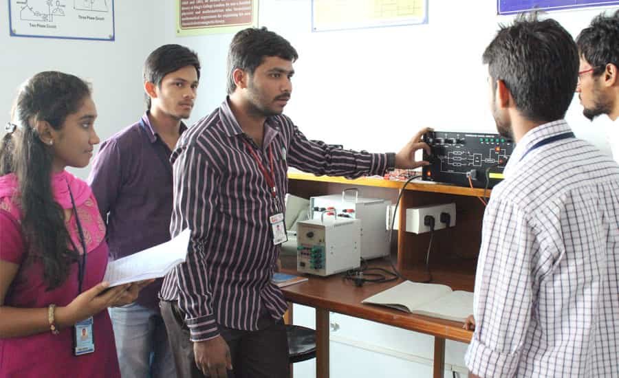
|
The goal is to gain hands-on experience with the design and implementation of a control system. We will use the discrete-time approach, in which the system to be controlled is modeled both by discretizing an available continuous-time physical model and by using system identification. A systematic, MATLAB-supported design methodology is followed, using a state estimator (observer) and a state-feedback controller. |
| Major Equipments | 1. Time Response of Second Order System study unit. 2. Characteristics of Synchros Synchro transmitter and receiver pair 3. Effect of feed back on DC Servo Motor. 4. Dc servomotor speed torque characteristics study unit 5. Effect of P,PID,PID controller on a second order system:PID controller Trainer 6. Lag and Lead Compensation – magnitude and phase plot lead lag network study unit. 7. Characteristics of Magnetic Amplifier. Magnetic Amplifier study kit. 8. Characteristics of AC Servo Motor. 9. AC servo motor speed torque characteristics study unit. 10. Temperature Controller Using PID. 11. Transfer Function Of DC Motor consists of DC motor with mechanical loading arrangement- 0.5hp/220v/1500rpm. 12. Dc motor controller module. 13. Digital tachometer. |